





Blog
Ground Screw Dimensions and Steel Grades for PV Projects
Date: 2026-10-20
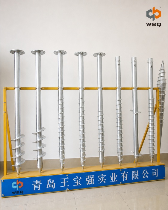
Two ground screws can have the same overall length and shaft diameter yet differ in wall thickness, steel grade, helical geometry, and top connection. Those differences affect how they carry loads, deform, and withstand installation. A quote that lists only length and diameter leaves much of the technical specification unresolved.
For fixed-tilt and tracking PV systems, ground screw dimensions and steel grade need to be considered together with foundation reactions and site conditions. The aim is to establish a specification that meets structural and ground performance requirements and can be installed with suitable equipment.
How dimensions affect ground screw performance
Shaft diameter and wall thickness
For a tubular shaft, outside diameter and wall thickness together define the steel cross section. They affect axial resistance, bending and torsional resistance, and stiffness. At the same outside diameter, changing wall thickness changes the section properties; the two screws are not structurally equivalent.
Wall thickness also matters to local buckling and to the section remaining after any corrosion allowance required by the design. Compare specified thickness, tolerances, and the section used in calculations, rather than outside diameter alone.
For a catalog example, the WBQ F76 product page lists a 76 mm pipe outside diameter, 3–4 mm wall thickness, and lengths of 1,200, 1,600, 1,800, and 2,000 mm. These catalog values apply to the F76 model; the selected dimensions, combination, and tolerances should be confirmed in the quotation and drawing.
Total length and embedment depth
Total length is the product dimension. Embedment is the portion installed below the specified ground level, while exposed length is the portion above it. Drawings should identify the measurement points, finished ground level, and connection elevation so that the same terms mean the same thing to the designer, supplier, and installer.
A longer screw may reach a suitable soil layer or engage more ground, but the resulting foundation capacity depends on the soil profile, installed geometry, and load transfer mechanism. Greater depth may also introduce installation difficulties in dense layers, gravel, or buried obstructions.
Exposed length affects the shaft’s unsupported condition. A horizontal force applied higher above ground creates a greater moment about ground level for the same force. An offset between the connection and shaft centerline can add bending as well. The location and direction of the load therefore matter as much as its magnitude.
Helical geometry and pitch
The helical section helps the screw advance during rotary installation and transfer load to the surrounding ground. Its outside diameter, flight thickness, pitch, and extent along the shaft are separate dimensions. Pitch is the axial distance between corresponding points on successive turns of a helical flight. Actual installation advance per revolution can differ from the geometric pitch.
A continuous helical flight and separate, spaced bearing helices have different geometries. A design method developed for one arrangement should not be applied to another without confirming its applicability. Comparing only the largest helical diameter can overlook differences in the effective load transfer area, steel resistance, and soil interaction.
Larger helical dimensions can change both ground resistance and the effort required for installation. Pitch also interacts with shaft geometry, soil conditions, rotation, and downward pressure. There is no reliable general rule that assigns a small pitch to hard soil or a large pitch to soft soil. Use the proposed product drawing and relevant design or test evidence to assess the configuration.
Choosing between Q235B and Q355B
WBQ’s F76 product page lists Q235B and Q355B as material options. Q355B generally offers higher specified yield strength than Q235B. Select the grade based on the foundation design requirements rather than the application category alone.
Ground screw steel grade selection should consider the cross section, member length, combined forces, buckling, connection resistance, and manufacturing requirements. Where shaft strength controls, a higher grade may be one possible design adjustment. Changing diameter, wall thickness, or the structural arrangement may also be relevant. Each option needs to be assessed against the governing requirement.
Strength and stiffness are different. Yield strength concerns the onset of permanent deformation; elastic stiffness concerns movement under load. For the same geometry, changing between these structural steel grades does not produce an increase in elastic stiffness proportional to the increase in yield strength. If excessive displacement controls, changing grade alone may leave the problem unresolved. It also does not increase the resistance supplied by the soil.
Material properties must be tied to the specified product standard, thickness, and delivery condition. The numbers in a grade name are not a fixed performance guarantee for every component. For export projects, acceptance of a Chinese grade or an alternative material must be established against the project specification; similar grade names do not establish interchangeability.
Weld performance needs separate attention. Material chemistry, including carbon equivalent where relevant, thickness, joint details, consumables, and welding procedures affect the finished joint. A higher shaft grade does not automatically increase the resistance of the flight weld or top connection. Toughness requirements should also reflect the service temperature and project specification.
Comparing complete specifications
Illustrative comparison: two quotes list the same total length and shaft outside diameter, but one specifies a different wall thickness, steel grade, helical flight, or top plate. They cannot be treated as the same technical offer until those differences have been resolved. The following parameters provide a practical basis for comparison.
|
Parameter |
Why It Matters |
What to Confirm |
|
Shaft diameter
and wall thickness |
Define cross
section, stiffness, and resistance to combined forces. |
Outside
diameter, thickness, tolerances, and design section. |
|
Total length
and embedment |
Affect
installed position, soil engagement, and exposed length. |
Measurement
points, target embedment, and connection elevation. |
|
Helical
geometry |
Affects soil
interaction and installation demand. |
Flight
diameter, thickness, pitch, extent, and applicable design basis. |
|
Steel grade |
Sets material
strength and other specified properties. |
Grade, product
standard, delivery condition, and required evidence. |
|
Top connection |
Transfers
forces between the support and shaft. |
Plate and hole
dimensions, fasteners, welds, and load eccentricity. |
|
Corrosion protection |
Affects durability and the
section available over time. |
Exposure, design life,
coating requirements, and any corrosion allowance. |
WBQ’s ground screw series are F/N/U/D/Irregular. A series name helps identify the product family, but the agreed drawing and material specification define the supplied configuration. For PV supports, top plate geometry and fasteners must accommodate the required forces and connection arrangement.
Corrosion protection should reflect soil and atmospheric exposure, design life, and project requirements. Soil moisture, pH, and salts can affect buried steel and zinc coatings. A coating thickness alone does not establish the same service life at every site.
Confirming loads and site suitability
Start with foundation reactions for the relevant support locations and load combinations. Identify whether values are service or working loads, factored design loads, or test targets. Keep axial compression, uplift, horizontal force, and bending moment separate, with a defined reference level and direction. Use force units such as kN and moment units such as kN·m, rather than an unexplained load in “tons.” Include the permitted movements and rotations.
Structural verification addresses the shaft, helical steel, welds, and connections under the relevant forces and deformation limits. Geotechnical verification addresses compression, uplift, lateral response, and movement in the actual ground. Installation verification addresses whether the specified depth, position, and installation quality can be achieved. Satisfying one does not establish the other two.
The ground assessment should consider the soil profile and groundwater, including weak layers, fill, seasonal effects where relevant, and obstructions. For overseas projects, use the applicable local requirements, adopted design standards, and project documents to establish the design basis.
Using installation trials and load tests
Ground screws are installed by rotation with appropriate downward pressure. Match the screw’s allowable installation torque and drive connection to the equipment’s operating capability at the intended speed, hydraulic conditions, and site access. A machine’s maximum advertised torque alone does not establish compatibility. Confirm how obstructions or refusal will be handled without exceeding product limits.
Trial installations can reveal whether the proposed geometry reaches the intended depth and maintains position. Record the actual screw configuration, depth, installation conditions, and observations. Equipment output torque is not itself a verified foundation capacity. Any torque-based capacity assessment needs a relationship validated for the relevant screw configuration and site conditions; a universal conversion factor is inappropriate.
Select load tests to address the performance that needs verification. Depending on the project, that may involve axial uplift, compression, or lateral testing. The loading procedure, target loads, measurement method, and movement criteria should follow the project’s adopted test requirements. There is no single test combination or fixed load multiplier suitable for every PV project.
Before ordering, agree which drawings, material evidence, dimensional inspection records, and coating or other quality records are required and available for the quoted supply. Material evidence supports material verification; factory inspection supports manufacturing checks; site tests address installed performance. Management system or manufacturing credentials do not replace project design or site validation.
Discuss your PV ground screw requirements
Send WBQ your project location, available geotechnical information, foundation loads, layout or connection drawings, estimated quantity, and delivery requirements. Share the information you already have so we can discuss the proposed supply and identify the remaining technical details. Final specification selection must follow the project’s design and validation requirements.
Browse our ground screw range or contact WBQ.