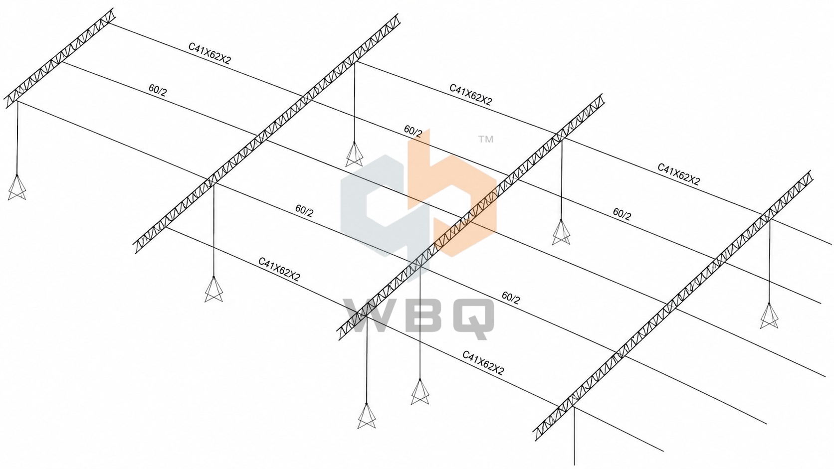
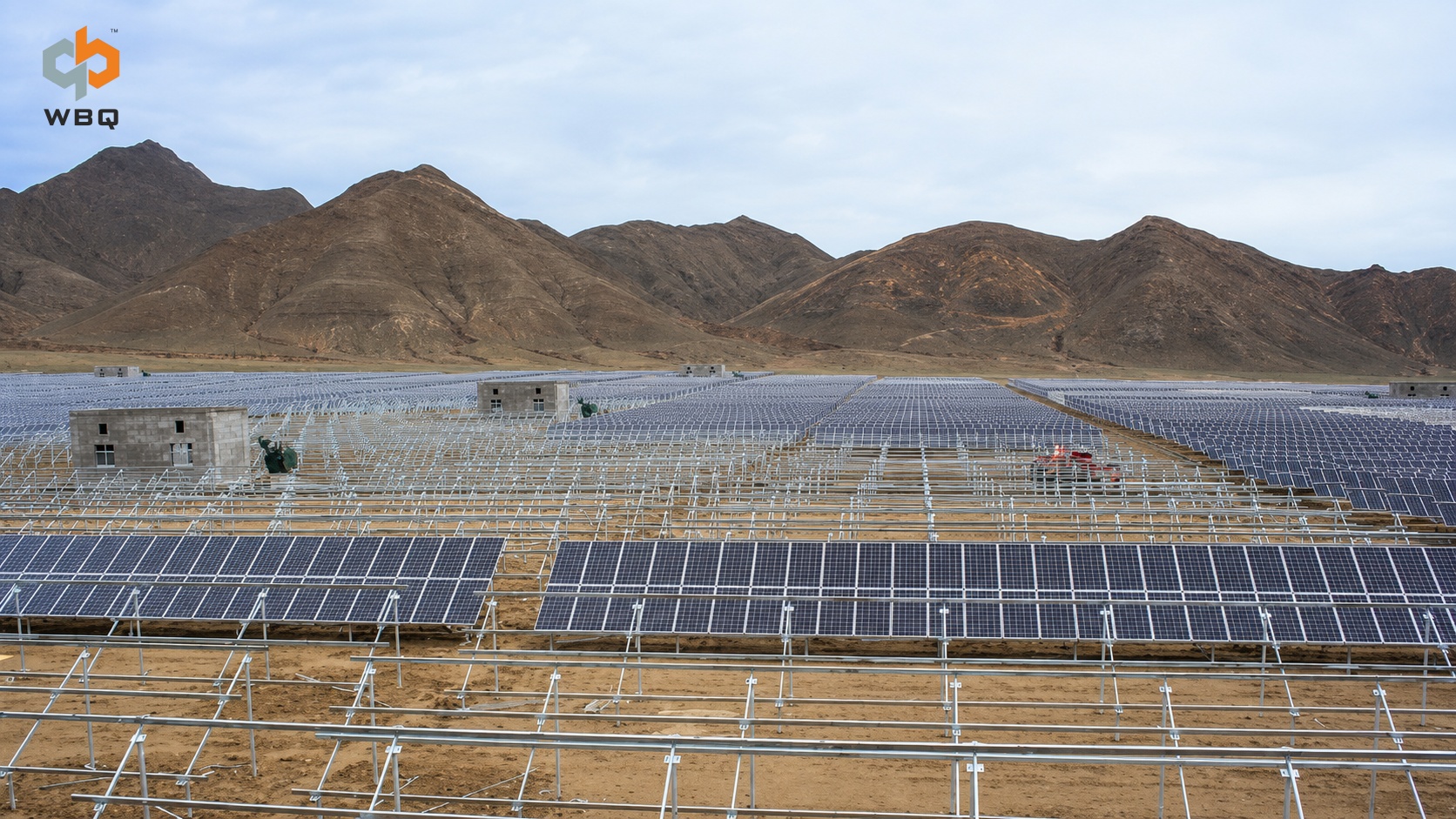
 Ground-mounted solar mounting system at a mountainous project site
A solar mounting system may appear to be a straightforward assembly of posts, beams, rails, and fasteners. In practice, however, a mounting structure cannot be transferred from one project to another without first checking the conditions that define its use.
Even projects of similar capacity may require different structural layouts and connection details because of changes in module dimensions, terrain, array tilt, foundation type, environmental loads, or applicable standards.
A workable solar mounting system therefore does not begin with selecting a section size and fitting modules onto it. It begins with the project conditions and turns those inputs into coordinated components, connection details, production drawings, and installation requirements.
The Mounting System Must Fit the Site
Project location affects far more than transportation distance.
Terrain, elevation changes, drainage, access roads, and material storage areas can all influence array layout and installation planning. Flat sites are generally more suitable for standardized components, while sloping or uneven ground may require different post lengths, wider adjustment ranges, and closer coordination between adjacent arrays.
The foundation type should also be confirmed early. Ground screws, driven piles, and concrete foundations have different connection requirements. The post base, hole positions, and allowable installation tolerances must be coordinated with the selected foundation.
When the foundations and mounting system come from different suppliers, interface dimensions and installation tolerances should be agreed upon before production. Otherwise, inconsistencies may only become apparent during manufacturing or site installation, resulting in drawing revisions, field modifications, rework, and schedule delays.
Module Selection Affects the Structural Layout
Module length, width, thickness, and weight are essential inputs, but overall dimensions alone are not enough.
Mounting-hole positions, permitted clamping zones, and support requirements vary by module model. These differences can affect rail spacing, clamp locations, connection details, and support spans.
If the module model changes, the review should cover more than whether the replacement module physically fits the structure. Key items include:
• Module orientation and array configuration;
• Mounting-hole positions or permitted clamping zones;
• Rail spacing and module support locations;
• Compatibility between clamps, connectors, and module frames;
• Mechanical installation requirements specified by the module manufacturer.
This is particularly important for larger-format modules. Increased weight and exposed surface area may affect structural loading, handling, and installation planning. Module wattage alone is not a sufficient basis for selecting or adapting a solar mounting system.
Wind and Snow Loads Must Be Reflected in the Structure
Descriptions such as “high-wind area” or “heavy winter snow” cannot replace defined design parameters.
Project location, basic wind speed, snow load, terrain category, array height, tilt angle, and applicable standards form part of the project design basis. A change in any of these inputs may affect structural members, connection plates, fasteners, and foundation interfaces.
Array tilt, for example, influences both energy generation and the way wind acts on the structure. Once the tilt angle has been selected, it should be checked together with the module layout, ground clearance, and local environmental conditions rather than adjusted independently at a later stage.
These requirements must ultimately be reflected in the posts, beams, rails, connections, and fasteners. Reviewing only the thickness or section size of an individual component does not confirm that the entire PV mounting structure is suitable. The connections and load path must remain consistent with the approved project conditions and intended installation method.
How Site Conditions Shape a Solar Mounting System
Corrosion Protection Should Match the Environment
Solar mounting systems remain outdoors throughout their service life. Material selection and corrosion protection should therefore reflect the site environment and the project’s technical requirements.
An inland site, a coastal high-salinity environment, and a location with high humidity or other specific corrosion risks should not automatically receive the same protection system. Project documentation should clearly define:
• Materials and surface treatments for the main structural components;
• Applicable coating standards and acceptance requirements;
• Fastener materials and corrosion protection;
• Treatment of cut edges, welded areas, and secondary processing points.
Where galvanized steel is specified, hot-dip galvanizing after fabrication should be distinguished from continuously galvanized material. The two processes follow different production methods, standards, and acceptance criteria and should not be evaluated under the same general description.
Surface color alone is also not a reliable basis for judging corrosion protection. Material certificates, coating type, specified thickness, surface integrity, and fabrication quality should be checked against the contract, approved drawings, and applicable project requirements.
Production Drawings Must Also Work on Site
Once the structural requirements have been established, the drawings must address how the system will be manufactured, delivered, and installed.
Component lengths, hole positions, connection directions, fastener specifications, and installation sequences should be clearly shown in the production and installation documents. For utility-scale ground-mounted solar projects, component standardization, packaging, array identification, and unloading sequences may also affect execution efficiency.
Too many component variations increase the difficulty of production control and site sorting. Excessively long or heavy components can complicate container loading, transportation, handling, and manual installation. If the connection details provide insufficient adjustment for foundation tolerances, site assembly may still be difficult even when every component has been manufactured according to the drawing.
Optimizing a solar mounting system does not simply mean using less material. Structural requirements, manufacturing efficiency, logistics, and installation practicality must be considered under the same project conditions.
How WBQ Supports Solar Mounting Projects
Within the WBQ product portfolio, solar mounting structures are coordinated with the foundations, manufacturing requirements, and intended site installation conditions.
During project discussions, WBQ works with the module information, array layout, foundation type, technical requirements, and delivery schedule provided or approved by the customer to coordinate product configuration and manufacturing supply.
For projects involving both solar mounting structures and ground screws, WBQ can also coordinate interface dimensions, connection details, and installation tolerances between the mounting posts and foundations. This helps reduce mismatches that may occur when the two product groups are sourced separately.
WBQ’s Tianjin Racking Manufacturing Base supports the production and supply of solar mounting components within the group’s manufacturing system. Before production begins, confirmed materials, component specifications, hole positions, connection parts, packaging requirements, drawings, and bills of materials should remain consistent.
If the project conditions change, the related technical documents and production information must be updated accordingly. Early confirmation of these requirements helps reduce discrepancies between manufacturing documents, delivered components, and actual site conditions.
WBQ’s role in this process is focused on product and manufacturing coordination based on confirmed project information, together with mounting-to-foundation interface coordination where applicable. Any project-specific structural design, calculation, approval, or certification requirements should be confirmed separately according to the agreed scope of supply.
Quotations Must Use a Consistent Design Basis
During the inquiry stage, project capacity may already be known while the module model, array arrangement, or environmental loads remain provisional. Any mounting proposal and quotation prepared at this stage will therefore also be based on provisional information.
If the module is replaced, the tilt angle is adjusted, the foundation type changes, or the wind and snow parameters are updated, component specifications, material quantities, and delivery arrangements may need to change as well.
Before comparing quotations from different solar mounting system suppliers, project teams should confirm that each proposal uses the same basic conditions:
• Project location and applicable standards;
• Module model and array configuration;
• Wind load, snow load, and other design conditions;
• Connection between the mounting structure and foundation;
• Material and corrosion-protection requirements;
• Supply scope and planned delivery schedule.
Quotations are only meaningfully comparable when they are based on consistent project information. The same discipline helps keep manufacturing, delivery, and installation aligned with the approved requirements.
From Project Information to a Manufacturable and Installable System
A solar mounting structure connects the modules, foundations, and construction site. It also forms part of the load path that transfers environmental forces to the foundations.
Complete project information and clearly defined technical responsibilities make it easier to translate requirements into components, connections, drawings, and installation details. When critical inputs remain provisional for too long, later changes may affect material quantities, production schedules, delivery dates, and site planning.
At the inquiry stage, solar project developers, EPC contractors, and procurement teams should provide the following information whenever available:
• Project location;
• Module datasheet;
• Preliminary or approved array layout;
• Wind, snow, and other relevant design conditions;
• Foundation type and interface requirements;
• Required supply scope;
• Planned delivery schedule.
Providing this information is more useful than specifying a material grade or section size in isolation. It gives manufacturers a clearer basis for reviewing product configuration, production requirements, and supply conditions.
For an initial discussion with WBQ, preparing these project inputs in advance will help both parties define the supply scope, technical interfaces, and coordination requirements more accurately.