





Blog
Project Information Required for Ground Screw Load Testing
Date: 2026-09-01
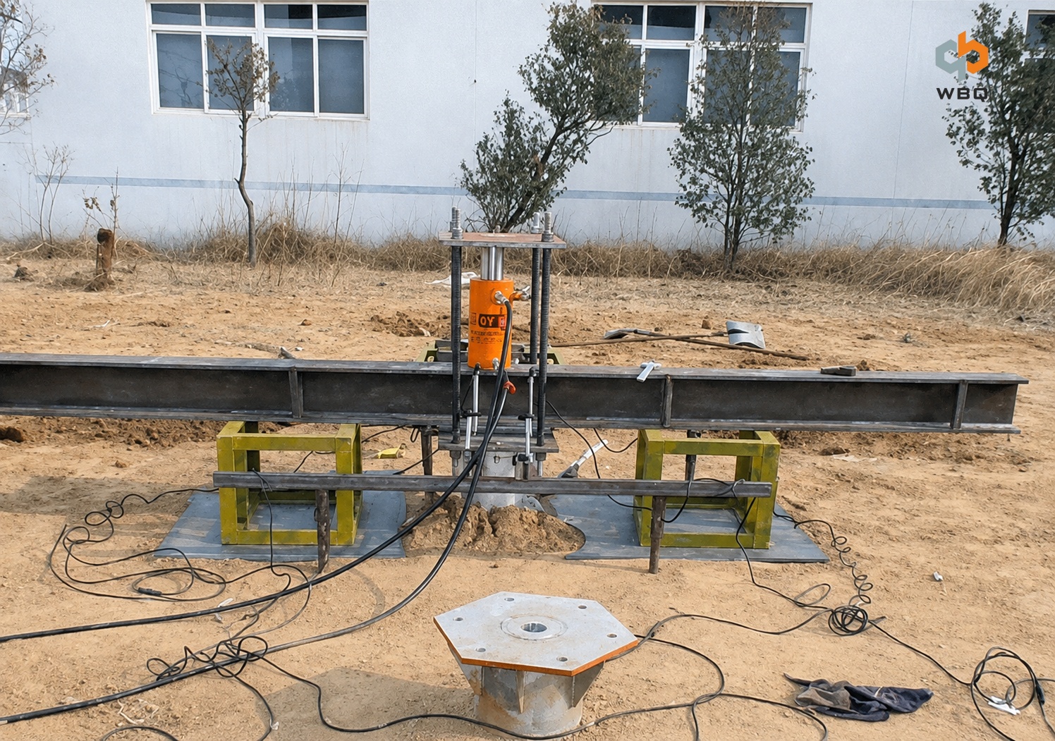
Learn what project information is needed before ground screw load testing to review load direction, test requirements, connections, and site conditions.
When requesting ground screw load testing equipment, buyers sometimes provide only the screw diameter, overall length, and a target load. These details are useful for an initial discussion, but they are rarely enough to determine whether the proposed equipment is suitable for the project.
The review also depends on why the test is being performed, how the load will be applied, the installed condition of the test screw, the maximum test load, connection details, reaction conditions, measurement requirements, and available working space. Two ground screws with the same diameter and overall length may require different arrangements if their embedment depths, head connections, or site conditions are different.
Providing this information at the inquiry stage helps the equipment supplier assess the proposed setup against the actual project requirements.
Why the Test Is Being Performed
Ground screw load testing may be carried out at different stages of a solar project.
Before the foundation design is finalized, on-site testing may provide data for comparing ground screw sizes, helix configurations, or installation depths. The results can support foundation selection by showing how a test screw responds under defined loading conditions at the project site.
Testing may also be specified to verify a required design capacity or to perform quality checks on installed ground screws during construction. Each purpose may involve different test screws, test locations, target loads, and uses of the resulting data.
The test purpose should be established before equipment is selected. An equipment supplier can assess whether a proposed setup is consistent with the information provided, but should not determine the required test load, loading procedure, allowable displacement, or acceptance criteria on behalf of the project engineer.
Load Direction Changes the Test Arrangement
A request for “ground screw testing” does not indicate how the screw will be loaded. The required direction must be stated.
An axial pull-out test applies an upward load along the ground screw axis and measures pull-out resistance and the corresponding displacement. A ground screw pull-out test is commonly specified where uplift performance needs to be evaluated.
An axial compression test applies load downward along the screw axis and records the response under compression. A lateral load test applies load from the side and evaluates lateral resistance and displacement.
Each direction may require a different connection, reaction arrangement, load application method, and displacement measurement position. These test categories should not be interpreted as capabilities of a particular piece of equipment. The intended direction must be checked against the confirmed equipment setup.
Ground Screw Data Required for Review
Outside diameter and overall length do not fully describe a test ground screw. The technical review should also consider wall thickness, helix quantity and dimensions, installation depth, head or top connection, and current installation status.
Overall length and installation depth are not interchangeable. Overall length refers to the full length of the screw. Installation depth or embedment depth refers to the portion installed below ground. The exposed section can affect both the connection position and the space available for the test arrangement.
If the screw has already been installed, the project team should provide the exposed head condition and available connection clearance. A model number should be supported by a ground screw drawing, head dimensions, and clear site photographs. These materials help identify connection requirements and possible interference from the ground surface or nearby structures.
Project teams preparing an inquiry may also refer to the information used to confirm ground screw specifications before procurement.
WBQ supplies a range of ground screw options with different structures and dimensions. Final selection remains subject to the approved foundation design and site conditions.
Load Requirements Must Come From the Project Documents
The maximum test load is necessary for equipment review, but it should not be considered in isolation. The applicable project documents should also define the design working load, load direction, loading increments, holding time at each step, displacement measurement requirements, data recording requirements, termination criteria, and test procedure.
These requirements affect how the load is applied and how the response is measured and recorded. A test that requires readings at specified load stages may have different recording requirements from one that requires a traceable load-displacement response throughout the loading sequence.
The required test load, loading procedure, allowable displacement, and acceptance criteria should be established by the project designer, structural engineer, or approved test procedure. The equipment supplier uses these requirements to review the proposed setup rather than deriving test parameters from the ground screw dimensions.
Project loads, ground conditions, and approval requirements vary. General load multipliers, holding periods, displacement limits, or pass-fail values should not be applied without reference to the governing project documents and applicable standards.
Site Conditions and Reaction Space
A geotechnical investigation and an on-site ground screw load test serve different purposes. The geotechnical investigation characterizes conditions across the project area. The load test records the behavior of a specific test screw under defined installation and loading conditions. Load testing may supplement the available site data, but it does not replace a complete geotechnical investigation.
Ground conditions may also vary across the same solar project. Differences in soil layers, compaction, fill, slope, or surface condition can affect the selection and distribution of test points. These decisions remain the responsibility of the project team and should follow the geotechnical information and approved test plan.
Equipment review also needs to consider access, ground level, slope, working space, clearance around the test screw, reaction arrangement conditions, test point locations, the available power source where required, and site safety restrictions.
Even when the load requirement appears compatible with the proposed equipment, the setup may need to be adjusted if the reaction arrangement cannot be installed or there is insufficient clearance around the screw. Site photographs and key dimensions should therefore accompany the ground screw drawing and load requirements.
Reviewing the Proposed Equipment Setup
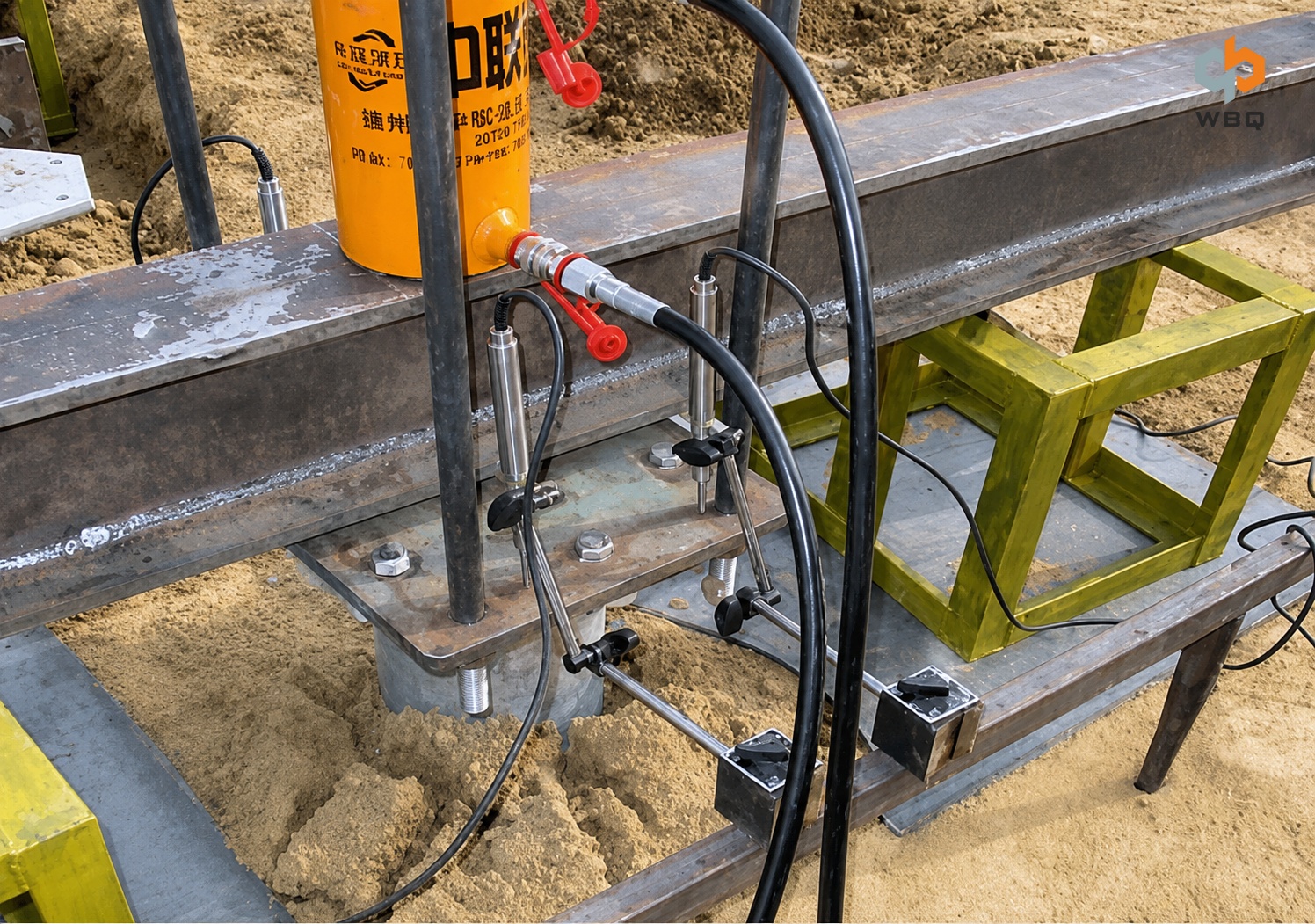
Ground screw load testing depends on several coordinated functions, including load application, reaction, connection to the test screw, load and displacement measurement, and data recording. Each function must be considered in relation to the approved test procedure and the available site space.
For projects considering the WBQ DT-10T load testing equipment, WBQ can review the submitted drawings, project test requirements, and site information to assess whether the proposed DT-10T setup matches the intended application. This technical review does not replace the approved test procedure, engineering assessment, or any required third-party testing.
Pre-Inquiry Information Checklist
Before requesting ground screw load testing equipment, prepare the following:
• Test purpose and load direction
• Ground screw drawing or complete specifications
• Overall length and actual installation depth
• Wall thickness and helix configuration
• Design working load and required maximum test load
• Loading requirements or approved test procedure
• Displacement measurement and data recording requirements
• Ground screw head and connection details
• Installation status and exposed head condition
• Site photographs and available working space
• Reaction arrangement conditions
• Available power source and applicable site restrictions
Project teams may send WBQ their test requirements together with the ground screw drawing and site information so the proposed DT-10T setup can be reviewed against the intended application.