





Blog
Information Often Missing from Ground Screw Pullout Test Equipment Inquiries
Date: 2026-09-10
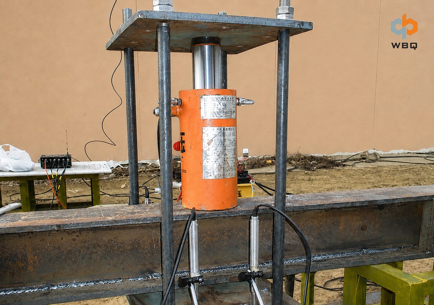
A ground screw pullout test equipment inquiry often begins with a photograph of the pile, its diameter and length, and a short request such as “We need a five-ton test.” That may be enough to start a conversation, but not to define the load requirement, pile-head connection, measurement method, reaction arrangement, or scope of supply.
Quotations can therefore appear comparable while covering different setups. One may cover only the hydraulic loading equipment; another may include connection hardware or measuring instruments. A useful quotation starts with a shared technical basis.
Why a Requested Test Capacity Is Not Enough
The inquiry should first identify the requirement as an axial pullout test. General descriptions such as “pile load test” or “static load test” do not establish the loading direction. Pullout, compression, and lateral tests may use different connections, reaction arrangements, and measurement methods. The buyer does not need to explain every test type, but should name the one being requested.
The stated capacity also needs an unambiguous unit and a clear basis. “Five tons” can be interpreted differently across markets and does not show whether the figure is a working load, maximum test load, or preferred equipment rating. The inquiry should retain the unit stated in the project documents and clarify its meaning rather than rely on an assumed conversion.
The maximum test load affects more than hydraulic jack capacity. It may influence the measurement range, connection hardware, and other load-bearing components. The rating of one component cannot confirm the capacity or suitability of the complete pullout test setup.
Working Load and Maximum Test Load Are Different Inputs
The design working load describes a design requirement for the foundation. The maximum test load defines how far the test is intended to proceed under the approved project requirements. These figures are related, but they are not interchangeable, and an equipment supplier should not derive one from the other without the governing project information.
The buyer should provide both values when available and identify their source, such as the design documents or proposed test plan. If the plan is still under review, the inquiry should state which value remains open so the supplier does not build a quotation around an assumption. The project location should also be included because the governing documents, terminology, and units may vary by market.
Loading increments, hold periods, displacement limits, and acceptance criteria come from the applicable standard, project documents, and responsible engineering parties. Equipment selection supports the required procedure; it does not establish or replace it.
The Drawing Must Show the Pile-Head Connection
A shaft diameter and overall pile length are not a connection specification. Whether the pile comes from the WBQ ground screw range or a project-specific design, the supplier needs a dimensioned drawing showing the shaft and wall thickness, helix configuration, pile head, flange dimensions, and bolt-hole quantity, diameter, and spacing. Other dimensions that affect load transfer should also be shown.
The pile-head connection deserves particular attention because it transfers load from the installed pile into the loading arrangement. Flanges, bolt patterns, threaded interfaces, and connection plates vary. A connection that fits one ground screw may not fit another pile with a similar shaft diameter.
Photographs can show whether the flange is accessible, whether mounting components remain on the pile, or whether the pile head has been modified or damaged. They cannot reliably establish bolt-hole diameter, spacing, plate thickness, or other dimensions needed for connection hardware. For connection review, the supplier should receive both the drawing and clear close-up photographs of the actual pile head.
Installed Conditions Affect the Proposed Setup
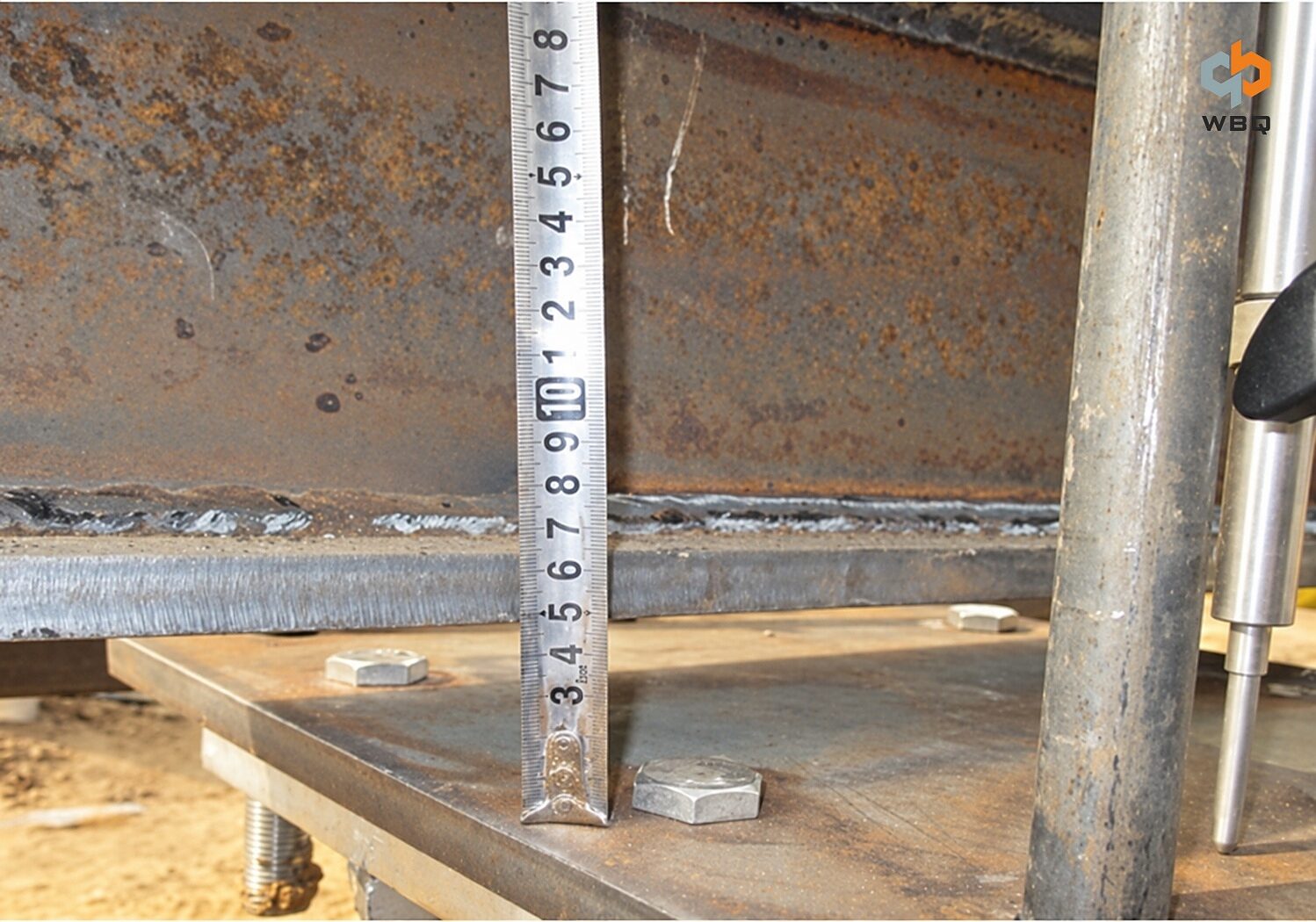
The product drawing describes the pile as manufactured; the installed condition shows what the equipment will encounter at the site. Design installation depth, actual installation depth, and exposed pile-head length can change the space available for the connection and loading components.
The inquiry should confirm whether the test pile is already installed and whether brackets, rails, foundations, or other components restrict access. Close-up photographs document the pile head, while wider views show the working area. Installation torque may be shared as construction information, but it is not a substitute for measured pullout capacity.
Connection hardware that appears suitable on a product drawing may still be difficult to install once exposed height and nearby obstructions are considered. Confirming these conditions early reveals potential clearance problems before supply.
Reaction Conditions Can Limit the Site Layout
Even with an appropriate loading range, the intended arrangement may not fit the test location. The reaction system provides the opposing force, and its supports need suitable positions around the test pile. Available width and height, ground slope, surface condition, access routes, nearby modules, utilities, and other obstructions can influence the layout.
A useful inquiry identifies the proposed reaction method and who will supply the reaction beam, frame, supports, or related site work. A dimensioned layout sketch should show the test pile in relation to available support locations. Wider site photographs help review access and obvious constraints, but they do not replace critical clearance dimensions.
The reaction system design, capacity verification, and approval remain the responsibility of appropriately qualified project personnel. WBQ may review equipment interfaces and layout constraints from the submitted information, but no reaction spacing, beam size, or support arrangement should be treated as universal.
Measurement Requirements and Supply Scope Need Separate Review
Hydraulic loading equipment applies the load, but that is only one function in a ground screw pullout test. A load measurement device measures or confirms the applied load. A displacement measurement device records movement in the loading direction. Connection hardware transfers the load, and the reaction system supplies the opposing force. Calibration and data-recording requirements come from the project test plan.
The inquiry should state how load and displacement are to be measured, including the required range, accuracy, calibration documentation, and manual or electronic recording requirements. It should identify any required raw-data or report format. A load cell, pressure gauge, or particular displacement instrument is not automatically the correct choice; the method must match the approved requirements and setup.
The buyer should separate the components needed to conduct the test from the items expected in WBQ’s quotation. Measuring instruments, connection hardware, reaction components, site services, installation assistance, and testing-party services may come from different parties. Identifying who will provide each item makes the commercial scope clearer and exposes gaps before an order is placed.
Information to Include With an Inquiry
Test Requirements
• Confirmed axial pullout test direction
• Project location
• Design working load and maximum test load with unambiguous units
• Applicable standard or project test plan
Ground Screw and Installation Details
• Complete dimensioned ground screw drawing
• Pile-head flange and bolt-hole dimensions
• Design and actual installation depth
• Exposed pile-head condition and site photographs