





Blog
Ground Screw and Solar Mounting Interface Checklist
Date: 2026-09-22
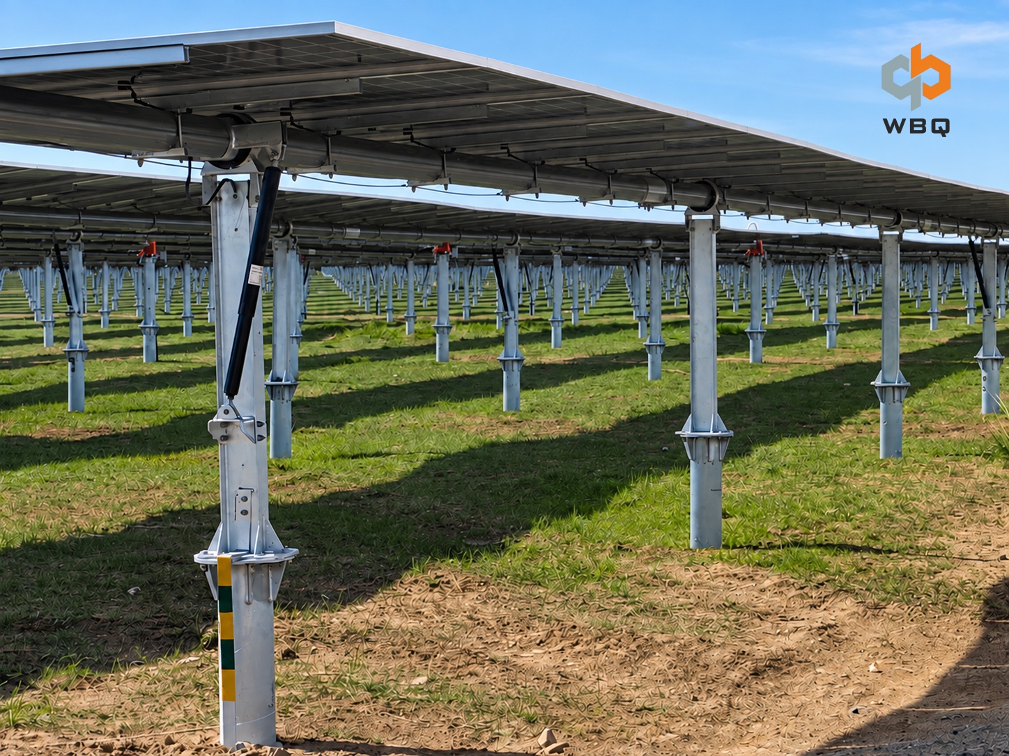
The ground screw specification may be approved, and the solar mounting structure may also have a complete drawing set. Yet the interface between them can still be unresolved. That gap often stays hidden until a trial assembly or field installation exposes a mismatch in the flange hole pattern, elevation, orientation, or fasteners. The ground screw, solar mounting structure, and interface therefore need to be reviewed as one connection before final drawings are released and production begins.
Interface review is not a second product inspection. Its purpose is to confirm that the ground screw top, mounting base, and any intermediate connection component can be assembled as designed and that the completed joint follows the intended structural load path. This is especially important when the foundation and mounting packages are designed, purchased, or supplied by different parties.
Approved Parts Can Still Produce a Mismatched Interface
Ground screw diameter, length, and top configuration describe the foundation component. The mounting supplier may separately define a post, support leg, or mounting base. Each component can comply with its own drawing without the two drawings establishing a workable connection.
A bolt may pass through both parts while the center-to-center spacing remains inconsistent. A plate may appear large enough but leave no room for a nut, washer, or installation tool. The installed top elevation may fall outside the adjustment available at the mounting base. Another recurring gap is supply responsibility: both suppliers may assume that the other party will provide the head plate, adapter bracket, or fasteners.
A product data sheet cannot resolve these conditions on its own. The connection should be shown in a single interface detail that identifies the ground screw centerline, top surface, mounting reference, fastener direction, and responsibility for every component in the joint.
Start With the Actual Top Connection
Ground screws may connect to a solar mounting system through a bolted flange, a side-bolted detail, a socket or sleeve, U-bolts, a separate head plate, or an adapter plate or bracket. The mounting base may be fixed or adjustable. None of these arrangements is universally preferable; each creates a different top geometry, hole layout, assembly direction, and load path.
For that reason, ground screws with the same shaft outside diameter are not automatically interchangeable. A different flange, side-hole arrangement, or head component can require a different mounting interface even when the screw body is unchanged. Adjustable parts also need defined limits. Slotted holes and adjustable bases should not be treated as an open-ended remedy for field variation. Their permitted direction and range must come from the approved design.
Review Flange Geometry and Hole Patterns on One Detail
The connection detail should define the ground screw shaft outside diameter; the shape and overall dimensions of the flange or top plate; plate thickness; hole quantity, diameter, and type; center-to-center spacing; bolt circle diameter where applicable; and the orientation of the complete hole pattern. Any center opening or other cutout also needs its dimensions and location. Ground screw diameter and length alone are not enough to confirm the upper connection.
The mounting side must be coordinated against the same reference system. The drawing should show the mounting base footprint and contact surface, along with the relationship between the ground screw centerline and the centerline of the post, support leg, or base. Plan views clarify hole distribution and orientation. Elevations or sections clarify plate thickness, bearing or contact conditions, bolt insertion direction, and installation clearance.
Matching numbers do not always mean matching geometry. One drawing may measure from a centerline while another uses an outside edge. A circular pattern may be dimensioned by bolt circle diameter, while a rectangular pattern uses spacing in two directions. The approved interface drawing should resolve this ambiguity rather than leave production teams to interpret it.
Assembly access deserves the same attention as hole alignment. There must be enough space to insert bolts, place flat washers and locking components, engage nuts, and use the specified tools in the intended sequence. No single hole diameter, spacing, plate thickness, or manufacturing tolerance applies to every project; those values must be taken from the approved structural and interface documents.
Coordinate the Mounting Base Adapters and Assembly Sequence
The solar mounting side of the interface may include more than a base plate. A support post or leg, connection plate, top plate, adapter plate, adapter bracket, and fasteners can all form part of the same node. The drawings should identify which parts are fixed, which provide adjustment, and whether adjustment is permitted in position, elevation, angle, or a combination of these.
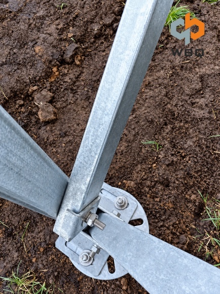
The detail should also show a practical assembly sequence. A connection that fits in a model may still be difficult to install if a support leg blocks bolt insertion or if the wrenching space disappears after another part is placed. Reviewing access and sequence before production can prevent a geometrically correct detail from becoming an impractical field connection.
The joint may transfer tension, compression, shear, and bending moment, depending on the approved structural design. Geometric fit alone does not establish structural capacity. Component sizes, contact surfaces, fastener requirements, and the complete load path remain subject to the project structural documents and the responsible design authority.
Treat Elevation Orientation and Tolerance as Interface Data
Once installed, the ground screw center location, design top elevation, projection above finished grade, verticality or specified inclination, flange-face orientation, and hole-pattern orientation become the starting conditions for the mounting structure. If the flange or holes must align with a tracker axis, table direction, or support line, that reference should appear clearly in the construction and interface drawings.
A deviation at the foundation can continue into the upper structure as misalignment, difficult assembly, or an as-built connection outside the approved design conditions. Post-installation survey requirements should therefore be defined together with the adjustment capacity of the mounting base or adapter. The surveyed condition can then be checked against the approved range before mounting work proceeds.
Project-specific tolerances must come from approved drawings, structural design documents, mounting system requirements, and the final interface record. Field hole enlargement, redrilling, cutting, or welding should not be used to force a connection unless the responsible project authority has reviewed and approved the change.
Specify Fasteners and Corrosion Protection as a Complete Package
A note stating that bolts are included does not fully define the connection. The interface documentation should state bolt diameter and length, property class for metric fasteners or grade for inch-series fasteners, quantity, nuts, flat washers, locking method or components, and installation direction. Any tightening procedure or torque requirement, along with any restriction on fastener reuse, should be tied to the approved drawing, fastener specification, or mounting system documentation. Metric property classes and inch-series grades should not be converted or mixed without project approval.
Corrosion protection must remain continuous across the ground screw top, flange, connection plate, adapter, and fasteners. The review should consider the specified materials and finishes, compatibility between fastener coatings and the main steel parts, hot-dip-galvanized finishes where applicable, and dissimilar-metal contact where relevant. If approved field work damages a coating, the repair method needs to follow the project requirement. Details that can trap water, along with drainage around the connection, should also be reviewed before the interface drawing is approved.
Pre-Production Interface Review Checklist
• Ground screw general arrangement drawing and flange or top-connection detail
• Mounting base, support post, or support leg drawing
• Ground screw-to-mounting-structure connection detail
• Connection plate, top plate, head plate, or adapter drawing
• Flange shape, dimensions, thickness, hole type, hole spacing, and orientation
• Fastener specification, quantity, installation direction, and locking components
• Design top elevation, projection above finished grade, and orientation requirements
• Ground screw location, verticality or inclination, and installation tolerances
• Approved adjustment direction and range
• Design and supply responsibility for ground screws, mounting components, adapters, and fasteners
• Drawing numbers, approved revision numbers, approval status, and effective date
• Responsible reviewers and the interface approval record
Freeze the Interface Before Production
This checklist is intended to confirm one connection node, not the full bill of materials, packaging plan, or shipment inspection. The ground screw supplier, mounting supplier, installation team, and project technical representatives should review the same detail. If a discrepancy is found, the responsible party and revised drawing should be identified before fabrication is released.
This article helps project teams recognize interface coordination items. Final dimensions, tolerances, tightening requirements, and connection design must follow the approved project drawings, structural design documents, technical agreements, and interface requirements.
Bringing the ground screw, solar mounting structure, connection components, and fasteners into one coordinated review moves interface questions upstream, where they can be resolved before manufacturing and field installation. Based on approved project documents, WBQ can assist with checking the ground screw top configuration, mounting base, adapter requirements, and supply scope across the foundation and mounting packages. For a project-specific interface review, contact WBQ with the applicable foundation and mounting drawings.