





Blog
What Should Be Checked After Ground Screw Installation?
Date: 2026-07-21
Ground screw installation can move quickly, but completing the installation does not mean the foundation work is finished.
For solar projects, pile position, vertical alignment, top elevation and connection orientation can all affect the next stage of racking installation. Installation depth, site records and the handling of non-conforming piles are equally important when the work is reviewed or traced later.
A proper post-installation inspection should therefore confirm more than whether each ground screw has been driven into the soil. The installed foundations need to be checked against the project drawings, construction method and applicable acceptance requirements.
1. Confirm the installed pile position
The first step is to verify that each ground screw has been installed in the correct location.
Using the project layout and established survey references, the site team should check pile coordinates, spacing and overall row alignment. On large solar sites, sloping terrain and work divided across several installation zones can allow small positioning errors to accumulate.
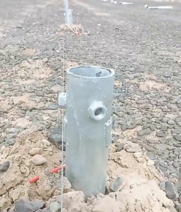
Ground screw installation referenced against the site setting-out line.
A misplaced pile may interfere with the installation of posts, beams or other solar racking components. If a deviation is identified, its extent and cause should be reviewed before any corrective action is taken. Forcing the upper structure into place is not always an appropriate way to compensate for an incorrect foundation position.
2. Check vertical alignment
Ground screws can move out of alignment during installation, particularly where the soil contains stones, compacted layers or other obstructions. Machine positioning and operating technique can also affect the final result.
Excessive inclination may create difficulties during structural connection and can change how loads are transferred through the foundation. Vertical alignment should therefore be checked with suitable measuring equipment rather than judged by sight alone.
Acceptable tolerances vary with the foundation design, racking system and project requirements. The final assessment should follow the approved drawings, installation procedure and inspection criteria for the specific site.
3. Verify the pile-top elevation
Pile-top elevation forms the transition between the foundation and the solar mounting structure.
If elevation differences within the same table or array exceed the available adjustment range, additional work may be required during racking installation. In some cases, the mismatch can affect the intended structural geometry.
On level sites, the relationship between adjacent pile tops is usually the main concern. On slopes or irregular terrain, the check should follow the designed profile and racking arrangement. It is not always correct to expect every pile top to be at the same elevation.
Recording the measured elevation by row, table or installation zone gives the racking team a clearer basis for the next stage of work.
4. Verify the actual installation depth
Installation depth is another key item in a ground screw inspection.
The site team should compare the specified depth with the actual installed condition, taking into account the original pile length, the exposed section and the installation record.
Where a pile cannot reach the intended depth because of rock, a hard soil layer or an underground obstruction, the affected pile number, actual depth and site condition should be documented. The issue can then be reviewed against the geotechnical information and foundation design.
Cutting the pile, relocating it or continuing installation without technical confirmation may introduce new risks. Any departure from the approved installation depth should follow the project’s agreed review and corrective-action process.
Related guidance: 6 Key Checks Before Procuring Ground Screw Foundations for Solar Projects
5. Inspect the pile head and connection interface
For ground screws fitted with flanges or other connection details, the upper interface should be checked before solar racking installation begins.
The inspection should confirm that:
• The flange or connection is facing the correct direction;
• Bolt-hole positions match the intended upper structure;
• The flange has not been visibly deformed;
• Connection surfaces are free from soil, stones and other debris;
• The pile head and welded areas have not been damaged during installation.
Finding these issues at the foundation stage is usually more manageable than discovering them after the racking components have arrived on site.
6. Check the exposed surface and corrosion protection
Ground screws may be scratched or marked during transport, handling and mechanical installation. The exposed tube, pile head, flange and welded areas should therefore be visually inspected after installation.
For hot-dip galvanized ground screws, differences in brightness or surface colour do not automatically indicate a coating failure. Inspection should focus on whether the coating remains continuous and whether there is visible exposure of the steel substrate, significant mechanical damage or red rust.
Any damaged area should be assessed and repaired in accordance with the project specification and the applicable coating repair procedure. The repair should also be included in the inspection record.
7. Review the installation records
A reliable inspection includes both the installed foundation and the documentation behind it.
Installation records should be traceable to individual pile numbers or clearly defined work areas. Depending on the project requirements, the record may include:
• Ground screw type and dimensions;
• Installation location and date;
• Actual installation depth;
• Installation equipment used;
• Unusual ground conditions or installation resistance;
• Details of non-conforming piles;
• Corrective action and reinspection results.
Some projects may also require installation torque, equipment readings or other operating data to be recorded.
These values can support construction control and later investigation, but a single machine reading should not automatically be treated as proof of foundation capacity. Its relevance depends on the ground screw design, equipment calibration, installation method, soil conditions and the engineering approach adopted for the project.
8. Complete load testing where required
Depending on the foundation design, geotechnical conditions and project specification, installed ground screws may be subject to pull-out, compression or lateral load testing.
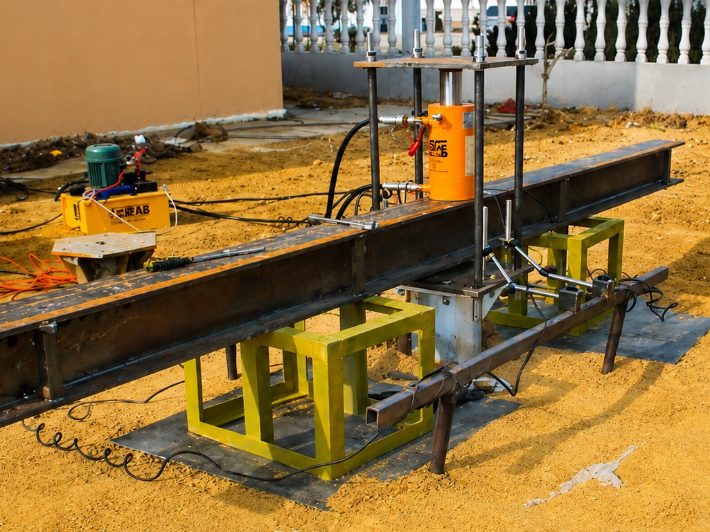
WBQ pull-out test equipment and data collection setup.
The selection of test piles, test quantity, loading procedure and acceptance criteria should be defined by the project engineer or the applicable technical documents. Test results should remain linked to the corresponding pile location, ground screw specification, installation depth, soil conditions and installation record.
A test report without clear pile identification provides limited value when the project team later needs to compare performance across different areas of the site.
If a test result falls outside the project requirement, the cause should be investigated before a corrective solution is selected. Soil variation, pile geometry, installation depth and the installation process may all need to be considered.
Non-conforming piles: record first, then review
When an inspection identifies an issue with pile position, alignment, elevation, depth or the connection interface, the affected pile should first be marked and recorded. Where necessary, work on the corresponding racking position should be paused.
The decision should not be based only on whether the upper structure can still be connected. The project team also needs to consider whether the deviation may affect load transfer, foundation performance or final acceptance.
A consistent inspection checklist, non-conformance register and reinspection process helps reduce informal site decisions. It also gives engineering, construction and project management teams a common record for reviewing the issue.
A complete foundation check supports the next stage of work
Post-installation inspection is more than a visual check of the finished ground screw foundation.
Pile position, vertical alignment, top elevation, installation depth, connection details, coating condition and construction records all contribute to the quality of the installed foundation. Where required, load testing provides additional project-specific verification.
Checking these items before solar racking installation begins can reduce avoidable site adjustments and create a clearer record for quality review.
WBQ supplies ground screw foundations, pile-driving equipment and related technical support for solar projects. Product selection, installation planning and inspection requirements should always be determined with reference to the project’s geotechnical information, foundation design, loading conditions and site environment.
This article provides general engineering information and does not replace project-specific drawings, construction procedures or acceptance criteria.