





Blog
Ground Screw Manufacturing Process and Key Quality Checks
Date: 2026-11-03
A ground screw specification for a solar project may define the overall length, shaft diameter, wall thickness, top connection, and surface finish. These requirements guide the materials and fabrication work needed to produce the finished component.
Ground screw manufacturing typically includes cutting the steel, forming the shaft and helical section, assembling connection components, applying a surface finish, and inspecting the finished product. Details vary between models: tip geometry, helical construction, and top connections do not all follow the same design.
The following sections explain the main production stages and the features checked at each stage. The actual process and acceptance criteria should follow the product drawings, manufacturing documents, and purchase agreement.
Material Verification and Cutting
Before fabrication, the steel pipe’s material grade, outside diameter, and wall thickness need to be checked against the product specification. The material documentation should also correspond to the requirements in the order.
Material grade, pipe type, and product standard describe different aspects of the steel. Identifying one does not establish the others, so the purchase documents should state the relevant details clearly.
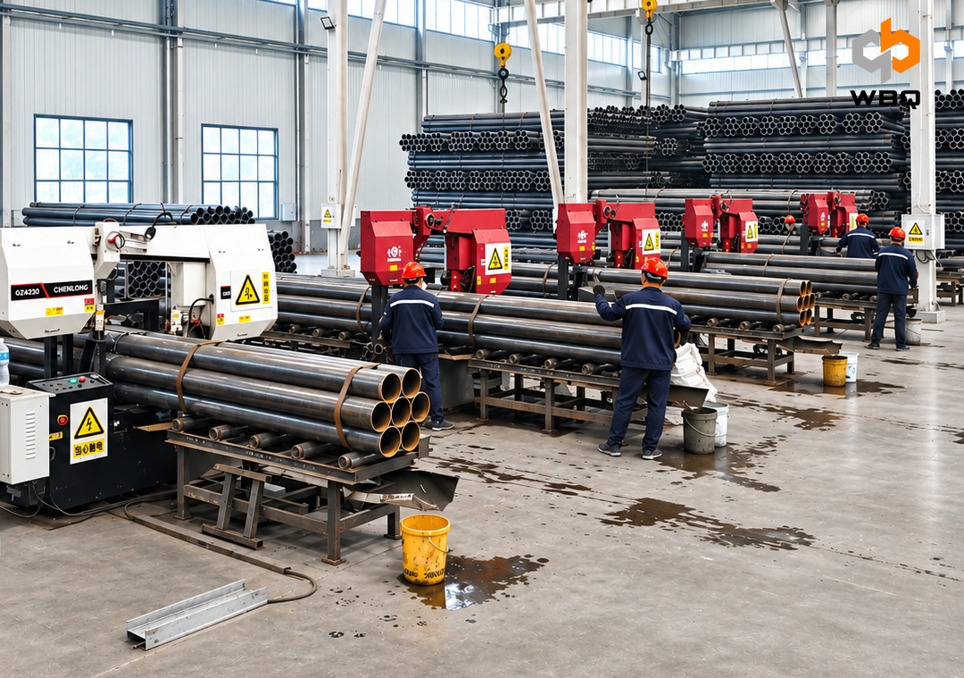
The pipe is cut to the length specified for production. Burrs and excess material at the cut ends are removed as needed for subsequent forming or welding. Pipes of different grades and dimensions should be kept distinct to help prevent similar-looking materials from being mixed.
Cut length is not necessarily the same as finished overall length. Forming and assembly can change the component’s geometry, so the cut length must account for the subsequent operations. The finished ground screw is then checked against the overall length shown on the final drawing.
For more on the relationship between shaft dimensions, steel grades, and product selection, see Ground Screw Dimensions and Steel Grades for PV Projects.
Forming the Tip and Helical Section
The method used to form a ground screw tip depends on its construction. For a product with a tapered tip formed from the shaft, the end of the steel pipe may be locally heated and shaped with tooling. After forming, the tip’s shape, taper, and changes in wall thickness can be checked against the applicable requirements.
These checks address a different condition from the incoming material inspection. The original pipe dimensions describe the steel before processing; the formed area needs to be assessed after the material has changed shape.
The helical section must also match the product drawing. Where it is formed from steel strip, checks can cover outside diameter, pitch, material thickness, and the condition of the formed section. Inspection can also identify cracks or unintended deformation outside the permitted limits.
The helical section is designed to follow a spiral shape. Inspection should distinguish that intended geometry from unwanted local twisting caused during fabrication. Components of different sizes should be kept distinct so they can be matched with the appropriate shafts.
The tip and helical dimensions help determine whether the finished product matches its drawing. Installation behavior and foundation performance for a particular project also depend on the design, soil conditions, and relevant verification.
Connection Components and Welded Assembly
Ground screw top connections vary by product. Where a flange is specified, its shape and bolt holes are manufactured to the drawing. Checks can include plate thickness, hole diameter, and center-to-center hole spacing.
The position of each component within the assembly matters as well as its individual dimensions. For a flanged ground screw, the flange’s position relative to the shaft—and the orientation of its hole pattern where specified—need to be checked. Where helical components are welded to the shaft, their positions along the shaft also need to match the drawing.
Checking the individual parts alone does not establish whether the flange is correctly positioned on the assembled ground screw. For the separate task of coordinating the finished ground screw with a mounting base, see the Ground Screw and Solar Mounting Interface Checklist.
Where welding is required, weld slag, spatter, and sharp projections are removed in line with the manufacturing process. The welds are then inspected against the drawing and applicable acceptance criteria. These may address weld location, continuity, and fillet weld size, where relevant.
Visual inspection can identify visible surface conditions, but it cannot determine the full internal condition of a weld. If a project requires nondestructive testing, the purchase documents should define whether testing is to be performed and specify its locations, method, extent, and acceptance criteria.
Surface Preparation and Hot-Dip Galvanizing
For products specified with hot-dip galvanizing after fabrication, the steel is prepared before immersion. Surface preparation addresses contaminants such as oil, rust, and mill scale and includes flux treatment as required by the applicable process.
A hollow steel shaft also requires attention to venting and drainage. Air must be able to escape, while processing liquids and molten zinc need a suitable path into and out of the component. The location and arrangement of openings should be considered alongside the tip, connection components, internal passages, and direction of immersion.
After preparation, the workpiece is immersed in molten zinc and then withdrawn so excess zinc can drain. The component’s geometry and the galvanizing process conditions both affect coating formation and surface condition.
Coating appearance and thickness are checked separately. A visual examination can identify uncoated areas, peeling, or surface conditions that affect use. Thickness is checked using an appropriate measurement method. The inspection scope and acceptance criteria should follow the standards and technical documents agreed for the order.
Finished Product Inspection and Documentation
After fabrication and surface treatment, the finished ground screw is checked against the applicable requirements. Depending on its construction and the order, inspection items can include overall length, tip dimensions, helical dimensions, connection-hole positions, weld appearance, and coating thickness.
For example, a flanged product can be checked against the specified flange dimensions and hole pattern. A different top connection calls for checks suited to its own geometry and connection features.
Inspection results need to be assessed against the final applicable drawings, purchase requirements, and acceptance criteria. Dimensional tolerances, coating requirements, sampling arrangements, and documentation needs can differ between projects and should be established when the order is agreed.
If a nonconformity is found, its nature and the applicable requirements should guide the decision on treatment and reinspection. A coating defect, for example, should be assessed against its condition and the agreed criteria before a repair method is selected.
Buyers and suppliers can also agree in advance which documents are required and available, such as material documentation, dimensional inspection records, or coating inspection records. Defining their scope helps the receiving team relate the records to the products supplied.
Manufacturing inspection checks the product against agreed fabrication and delivery requirements. For a solar project, ground screw capacity and site suitability still need to be determined through the project design, site conditions, and relevant verification.
To discuss WBQ ground screw products and supply requirements, share your available drawings or target specifications, quantity, connection type, surface treatment, and inspection requirements. If some details are not yet available, you can provide the information you have and discuss the remaining items with WBQ.